A Definitive Guide to Motorised Two Wheelers

Integrating Design Intent with Engineering Reality

A A

The Strategy of Intent: Beyond the Sketchbook

Design intent is the "North Star" of any automotive project, but it is a common misconception that it begins with a purely aesthetic sketch. In a sophisticated development environment, design intent is a data-driven strategy. It defines the vehicle’s "reason for being." Whether the goal is to create an ultra-frugal urban commuter or a high-performance flagship model, it is in fact the intent, which sets the boundaries that both designers and engineers must inhabit from day one.

Before a single line is drawn, the team establishes the User Persona. This includes ergonomics, price-point expectations, and performance benchmarks. If the intent is "aggressive sportiness," the engineering must support a specific weight distribution, while the design must communicate speed through its silhouette. This initial phase is where the "Product Brief" is born—a document that acts as an agreement between the creative and technical teams, ensuring that as the project evolves, the offering of the vehicle remains intact.

The Functional Skeleton: Negotiating Hard Points

Before the "skin" of the motorcycle is sculpted, the "bones" must be placed. This is the high-stakes negotiation of Hard Points. Hard points are the non-negotiable physical dimensions required for vehicle stability and safety: the wheelbase, the center of gravity, the swingarm pivot, and the volume required for the powertrain (whether ICE or EV).

Designers often push for a "tight wrap"—bodywork that clings closely to the mechanicals to create a slim, agile look. However, engineers must account for "clearance envelopes" (the space a part needs to move, like a wheel with suspensions). The iterative loop begins here. For example, if the design intent requires a low seat height, the engineer must find a way to package the rear shock absorber or the battery tray without ruining the bike's steering and handling. It is a game of millimeters where the silhouette meets the non-negotiable laws of physics.

Digital Synthesis: The Virtual Reality Check

In the modern era, the first "reality check" happens in a 3D virtual environment. Using Computer-Aided Design (CAD) and Digital Mock-ups (DMU), the design intent meets its first technical audit. This is where the various parts of the motorcycle are brought together, in other words, “integrated”.

A designer might envision a seamless, ventless side panel, but Computational Fluid Dynamics (CFD) simulations might reveal that the engine will overheat without airflow. Rather than seeing this as a "wrong" design, the iterative process treats airflow as a design driver. The vents are sculpted into the bodywork so that they fulfill the engineering requirement for cooling while enhancing the visual "speed" of the bike. Similarly, digital routing ensures that the complex "digital nervous system" (the wiring harness) doesn't interfere with the fuel tank's capacity or the rider’s legroom.

Another example is seen often in the design of the fuel tank, where the shape needs to consider the end to end movement of the handlebars while keeping adequate clearance from it. Here is where aesthetics and flow lines of the design meet the functional requirements of engineering.

Material Logic: The Specification Handshake

As the project moves from concept to reality, the focus shifts to Materials and manufacturing. A designer might want a specific matte texture or a deep metallic flake, but the engineer must ensure that the material can survive years of vibrations, stresses, UV exposure, salt spray, and engine heat.

This "specification handshake" involves selecting the right polymers, composites, or alloys. For example, a front fender needs to be flexible enough to withstand a stone impact but rigid enough not to flutter at 120 km/h. Designers and engineers collaborate to choose materials that satisfy the design’s "premium feel" while meeting engineering’s demands for weight targets and fatigue life. If the design intent calls for a lightweight frame, the engineering reality might dictate high-tensile steel or aluminium; the design must then adapt its aesthetic to celebrate those structural materials rather than hide them.

The impact of material selection affects design and manufacturing along with timelines and cost. For example, if a scooter needs to have its front facia panel in metal, the design acquires certain physical limitations due to the nature of the material and the manufacturing process involved. How a plastic flows in a mound or what shape is possible for a plastic fuel tank is vastly different from the shape and property of a tank made in steel. All such decisions are therefore never taken in silos.

DFM (Design for Manufacturing): The Reality of the Assembly Line

Design for Manufacturing (DFM) is where the "how" dictates the "what." A beautiful, complex curve on a 3D model is of no value if it cannot be mass-produced. In the two-wheeler world, three main processes among others, govern each with their own set of "reality checks":

Plastic Injection Molding

For body panels, designers must account for Draft Angles (the slight taper that allows a part to slide out of a mold) and Split Lines (where two halves of a mold meet). If a design is too "undercut," the part will get stuck in the machine.

Casting

Used for engine casings and wheels. The wall thickness must be uniform; if one area is too thick, the metal will cool unevenly, creating weak spots or "porosity."

Welding (manual or robotic)

The frame design must allow enough "welding gun access" for a robotic arm to reach in and create a perfect weld.
DFM isn't about making the design "simpler"; it's about making it "smarter" so it can be built at a rate of one bike every minute without a drop in quality.

Tooling Feasibility: When Geometry Meets Metal

Tooling Feasibility represents a critical phase in the development cycle where digital designs are converted into physical manufacturing assets. Unlike the prototyping stage, where parts may be produced through additive manufacturing or CNC machining, mass production requires a significant capital investment in steel molds, stamping dies, and casting patterns. At this stage, the primary objective is to ensure that the theoretical geometry can be reliably and repeatedly manufactured across high volumes without compromising structural integrity or aesthetic standards.

The Mechanics of Sheet Metal: Stamping and Deep Drawing

One of the most technically demanding areas of tooling feasibility is the fabrication of the fuel tank. A design intent that features sharp, aggressive creases requires the sheet metal to be stretched into a die under immense pressure. This process, known as Deep Drawing, is governed by the physical limits of the material.

  • Forming Limit Analysis: If a crease is too acute or a draw too deep, the metal reaches its Forming Limit. In these "Red Zones," the material thins excessively, leading to localized necking (becomes too narrow) or catastrophic tearing.
  • Compression and Wrinkling: Conversely, if the geometry causes a surplus of material that the die cannot effectively distribute, the metal will "pucker" or wrinkle. This is particularly common in complex concave surfaces where the metal lacks sufficient tension during the stroke.

Engineers utilize Forming Limit Diagrams (FLD) to simulate these stresses. If the simulation predicts a failure, the designer must increase the fillet radii or adjust the draw depth. These subtle geometric modifications, often measured in fractions of a millimeter, ensure a zero-percent scrap rate during a continuous production run.

High-Pressure Die Casting: Fluid Dynamics and Thermal Balance

For structural components such as engine casings, swingarms, and alloy wheels, the process involves High-Pressure Die Casting (HPDC). Molten metal is injected into a steel tool at high velocities, requiring precise management of fluid dynamics.

  • Flow Front Analysis: Engineers perform simulations to track the "flow front" of the molten alloy. If a section is designed too thin, the metal may solidify prematurely—a defect known as a "Short Shot"—preventing the mold from filling completely.
  • Thermal Management and Porosity: If there is a significant discrepancy in wall thickness across a part, the thicker sections will retain heat longer. As the metal cools and contracts, these "hot spots" can develop internal voids or Porosity, which compromises the component's mechanical strength. Feasibility studies often lead to the integration of cooling pins in the tool or the addition of structural ribs to the design to normalize cooling rates.
Plastic Injection Molding: Ejection Constraints and Surface Quality

The external body panels must reconcile aesthetic "Design Intent" with the mechanical requirements of Plastic Injection Molding. Because the part must be physically removed from a rigid steel tool, the geometry is strictly governed by the axis of ejection.

  • Draft Angles and Undercuts: Every vertical surface must possess a Draft Angle (typically 1.0° to 3.0°) to allow the part to slide out of the mold without friction damage. If a design features an "undercut"—a shape that hooks into the mold—engineers must design complex Sliders or Lifters. These moving steel elements retract before the mold opens, significantly increasing tooling costs and maintenance requirements.
  • Aesthetic Defects: If a plastic panel has a thick internal reinforcement rib, the cooling process can cause a Sink Mark (a shallow depression) on the visible outer surface. Tooling feasibility ensures these ribs are optimized for thickness (usually 40-60% of the wall thickness) to maintain a flawless class-A surface finish.
The Integration of Process and Form

Tooling feasibility is an exercise in Micro-Iteration. It is the process of refined negotiation where a designer may adjust a curvature and an engineer may reposition a "parting line" (where the two halves of a mold meet). These adjustments ensure the final component is not only a faithful representation of the original design intent but also a robust, cost-effective product capable of surviving the rigors of mass production.

The Prototyping Pulse: Testing "Intent" in 3D

Prototyping is the most emotional part of the cycle. It moves from Rapid Prototyping (3D Printing)—where parts are printed overnight to check for visual scale—to Alpha and Beta builds. An Alpha Prototype is commonly referred to as a "mule." It has the correct engineering (the engine and frame), but the "skin" might be rough. This is where engineers check if the bike actually works.

A Beta Prototype is of a higher level of detail, that brings the design and engineering together for the first time. This is where the team checks the the complete user experience with the vehicle. Does the rider's knee hit the fairing? Is the reach to the handlebars exactly what the design intent promised? If the "feel" is wrong, the design must be iterated, even at this late stage.

A Beta prototype also gets reviewed by other stakeholders that are more customer facing, like the branding & marketing team, who would interact with it rom the perspective of a customer and talk about things like perceived quality. The Beta prototype is a stage very close to production and is a critical junction of final corrections or improvements needed before going into mass production.

The Validation Loop: Real-World Failure as a Design Tool

Once a physical bike exists, it enters the "torture chamber" of Verification and Validation (V&V). The bike is sent to durability tracks, where it is ridden over cobblestones and jumps for thousands of kilometers to simulate a lifetime of abuse. Not all realities are discovered by digital simulations, which make real world validation tests that much more important.

Often, this reveals "Emergency Design Iterations." A bracket that looked perfect in CAD might snap under the specific vibration frequency of the engine. The mud flaps and fendors may not protect the vehicle from mud and dirt as expected. The display cluster visibility turns out to be bad during the afternoon. When these failures happen, the designers and engineers must huddle. The fix might involve adding a reinforcing rib in the plastic part itself(engineering team), which might change the look of the part (design team) but that in edffect could change the dimensions and clearances of the part with its surroundings(integration team). The "intent" is preserved by making the fix look like it was always part of the plan.

Regulatory Guardrails: The Global Compliance Filter

Every motorcycle must eventually pass through the filter of international law. Homologation standards for lighting, fender lengths, and noise levels are non-negotiable. For example, European or Indian safety norms might dictate a specific height for the rear turn signals or a specific "coverage area" for the rear mudguard. If the design intent was a "tail-less" minimalist look, the engineer must integrate the required reflectors and plate holders in some other way. The challenge here is to integrate these "legal requirements" so seamlessly that they look like aesthetic choices rather than afterthoughts.

The Final Synthesis: Delivering Product-Market Fit

The conclusion of this journey is the Final Handshake. A successful motorcycle is not one where the designer "won" or the engineer "compromised." It is a balanced machine where engineering constraints—like the need for a radiator or a battery heat sink—have been turned into beautiful design features.
When the product hits the showroom, the user should feel a singular, unified experience. They shouldn't see a "design" or an "engine" in isolation—they should see a machine that feels "right." This Product-Market Fit is only achieved when the friction of the iterative loop has polished away the rough edges of both the initial dream and the technical reality, leaving behind a functional work of art.

Previous 
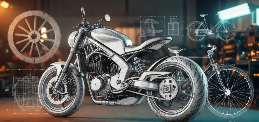
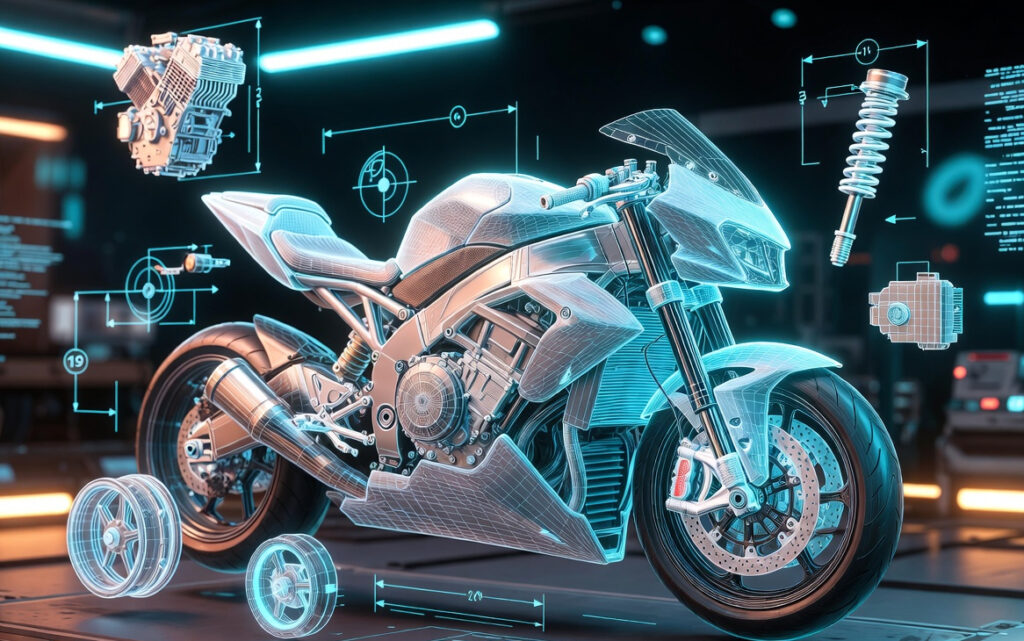
Transitioning from Concept Sketches to Prototype
Next Defining Quality Through Surface, Detail and Craft
Integrating Design Intent with Engineering Reality
Scroll to top